| The Voyage of INTREPID | |
| "Fitting the Bilge Panels" | |||
|
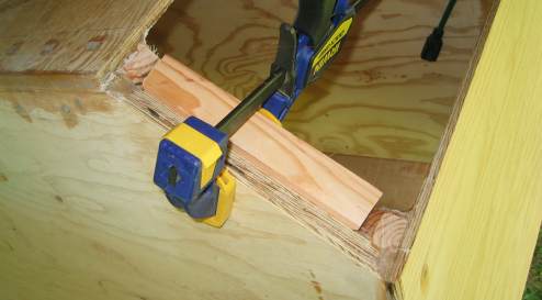
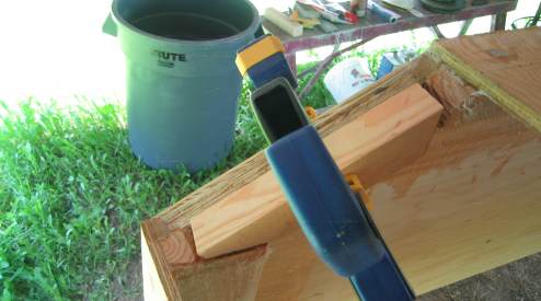
I set the height of the transom's bilge-section frame by running a 2 by 4 across the top of the transom, Bulkhead 17, and Temporary form 14, and raising the frame piece up to it. It was clamped and holes were pre drilled. I then applied epoxy and screws to permanently mount the piece to the transom.
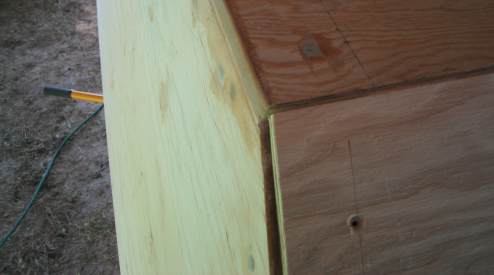
This is an inside view showing the bilge frame piece mating up with both the side frame and bottom frame of the transom.
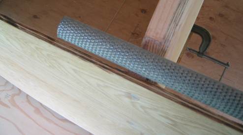
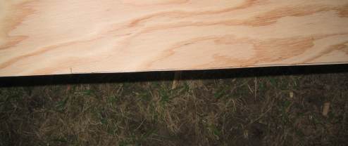
So that the bilge panel could lay properly between the bottom and side panels, a file was used to flatten the landings on all of the bulkheads and temporary forms.
I followed the plan's recommendations and cut the bilge panels a bit oversized, to be trimmed down to size later. This is actually to facilitate getting a good fit for the panels. However, I now realize that one to two inches oversize is probably not what the designer implied by his suggestion. A quarter to half inch oversize would have been more than adequate for these purposes.
The more hands you have the easier this part could be. As I am working solo, rope has become my best friend.
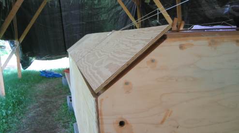
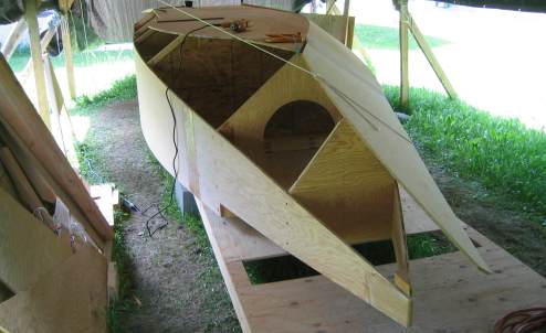
All cinched down, and giving a fairly respectable fit. I actually cut this piece to the lines on the plan and will adjust some areas that are binding.
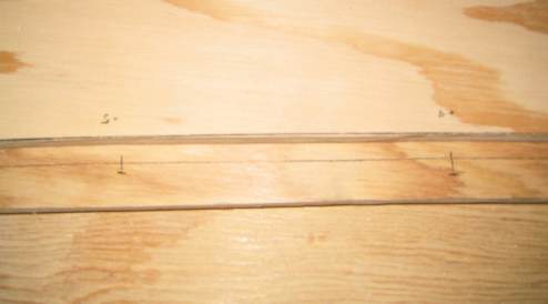
It might be difficult to see in this shot, but there is a reference line drawn along part of the bottom edge of this bilge panel. This section is affecting the panel's fit, and will need to be trimmed back a bit with the belt sander.
I am pretty satisfied with this side's fit. You can see a windlass bending the panel over onto Bulkhead 4. Something does not seem right to the bend at the bow between Bulkhead 4 and Temporary form 2, but we will see what happens when I get the port bilge panel up.
If you will recall, when I joined the bilge pieces together last month, one side was cut oversized around the drawn out lines; the other side was created just using
these oversized sections of plywood. This means that I have no reference lines on the second bilge panel, nor do I have the number of hands I would need to hold the
piece in place against the boat to draw appropriate reference (cutting) lines.
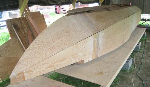
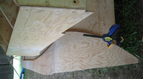
After connecting the plotted lines together, I had a good line to use for cutting purposes. I had to move the boat over to the right on the building table to get enough room to cut the port bilge on the table as well.
pre drilled holes in the transom, Bulkhead 17, Temporary form 14, Bulkhead 11, and Temporary form 8. Again, I used a setback of 5-millimeters for the bilge panel from the back edge of the transom. I will fill this section with epoxy putty that I can round over later.
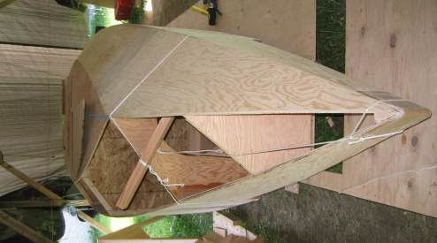
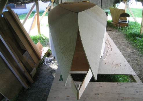
The reality here is that it is difficult to bend the bow bilge sections over into position to check for proper fit. I can hold one side down, and when I try to grab the other, the former pops up out of my control. Gotta get more ropes. Makes a good picture, though.
|