| The Voyage of INTREPID | |
| "Making Oars" | |||
|
I was perusing a boat building web site one day, and I came across an
article
written by Jim Michalak about making oars. I know I purchased a new motor for my boat, but considering the remoteness of where I will be
boating, it might not be a bad idea to have auxiliary power in the form of oars. I wrote Mr. Michalak and asked if it would be possible
to power the Dorado the same way he did his AF4. He thought it was a splendid idea, and recommended that I use 8-foot long oars mounted
low through oar ports located in the side of the boat.
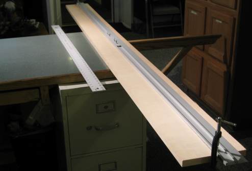
Getting back the article, it gave a design and dimensions for 7-foot long oars. Now I could have increased all dimensions by 14.3 percent to get the 8-foot length, or just increased the center section by 12-inches, but I decided to exercise boat builder's privilege and make the dimensioning choice a bit more complicated. I will keep the 8-foot length, but the overall width will increase from 2-inches to 2¼-inches. This will make the oar more square, as I will be using three laminations of ¾-inch clear pine. The square loom near the 5-inch handle will be 17-inches long vs. 16-inches, and the middle section will be extended by 10-inches. With the blade lengthened by 1-inch to 25-inches, the desired 8-foot length has been obtained. Also, the original design was for a 4-inch wide blade; this has been increased to 5-inches. If this proves to be too much, I can always cut it back. Draw a centerline down each plank. I used my edge guide as a straight edge as it is over 8-feet in length.
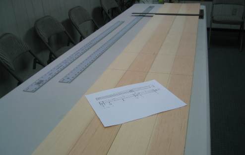
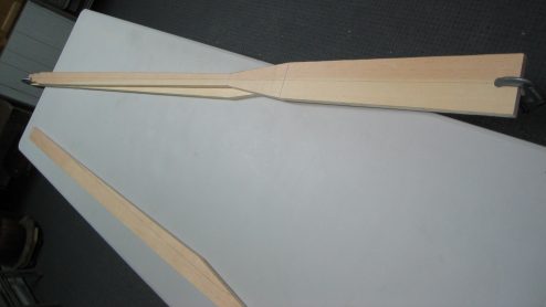
The picture below has two 8-foot lengths of 8-inch by ¾ inch clear pine laid out on a table with my new dimensions drawn in. These boards started out as a single 16-foot piece, which was cut in half at the lumberyard.
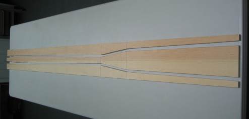
I used a jig saw to cut out the center blank of the paddle. The cheek pieces are to be laminated to the center piece. No need to draw in dimensions for the cheek pieces, except for overall length, as they will be trimmed down to the center blank's outline after they are glued to the center blank with epoxy.
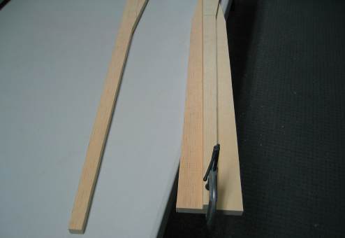
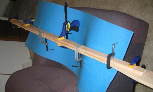
Change of plans. The directions say to glue up the laminations, then trim. I think it will be easier to cut the cheek pieces to size first. Align and clamp a cheek to the center blank.
Turn the clamped pieces over and trace the outline of the center blank to the overhanging areas of the cheek. Use a jigsaw to cut away the overhangs. Repeat the process with the other cheek. Make sure you label which cheek is to go to which side of the center blank for each oar.
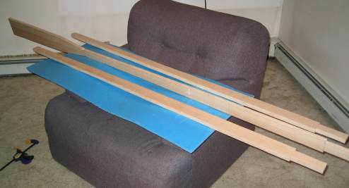
All three pieces for one oar are laid out together in preparation for laminating. The cheek pieces have already been trimmed to their final length, about to the neck of the blade where it opens up.
I opted to epoxy each cheek individually. It is hard enough to keep one cheek from sliding around, let alone two. I opened the windows to the room to cool it off; it was 10 degrees outside. Epoxy likes to cure at over 70 degrees, but high temperatures decrease working time tremendously. My 30-minute working time epoxy really felt like only 10. Let's see: 4 minutes to mix the epoxy, 6 minutes to spread it out, 2 minutes to align the cheek and get the first clamp on, 4 more minutes to get the rest of the clamps on, 2 minutes to realign the cheek because it slid off center, another 5 minutes to scrape the excess epoxy that squeezed out from the lamination on all sides ... and it is already too thick to work with ! Once everything was set up, I turned up the heat and closed the windows.
The next day I opened the windows to chill the room a couple of hours before I was to attach the second lamination. I also mixed the epoxy outside to keep it cold. The second cheek went on more easily.
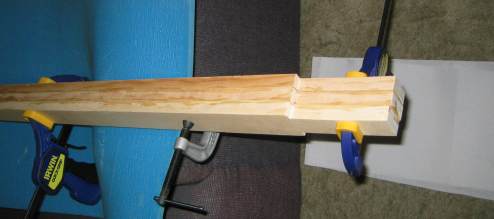
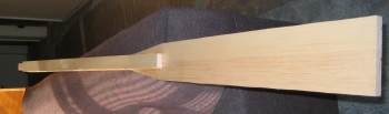
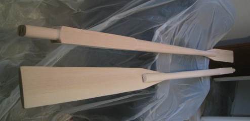
This is the first oar in-the-rough. I used my belt sander to square up the sides and handle where the laminations come together .
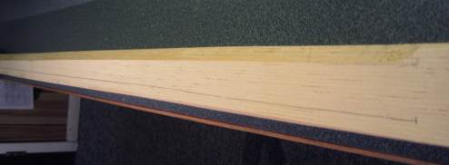
I drew two guide lines on either side of each corner ½-inch in, down the length of the oar shaft. I took a bench plane and planed the shaft below the square loom down to these lines making the four-sided shaft into an eight-sided shaft.
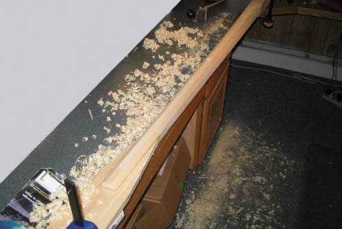
You can see the mess that was created from the shavings. Planing was a very satisfying although very tedious operation. I then used a wood rasp to knock down each of the corners on the shaft. The shaft is now rounded and has a natural taper from the square loom down to the blade due to the way the center blank was originally cut. I imagine that I could probably do the same "rounding" job in about 1/1000 th the time by using a router with an appropriate bit. I would like to get one, but these run a few hundred bucks.
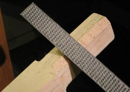
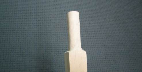
I continued with the wood rasp and did an excellent job of filing the handle down to the ½-inch lines, and then rounding everything over.
This is the finished handle. It is more oval than it is round. If the grip proves to be too large in use, I'll just break out the rasp again.
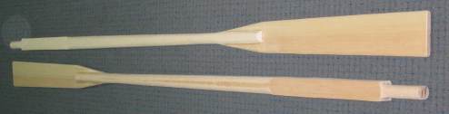
Just about done. The oars need a light sanding and a bit of feathering done to the blades. Then I can apply the varnish, attach the leathers, and make the oarlocks.
I had angle-planed the corners at the edge of each blade down to about 3/8ths of an inch. I used the belt sander to taper each blade to the side down to this measurement, leaving the blades thicker down the middle. The orbital sander was employed next with 180 grit sandpaper, smoothing everything out. After wiping the dust off with a damp cloth, I prepared to apply the first coat of spar varnish.
|