| The Voyage of INTREPID | |
| "Sides and Bilges" | |||
|
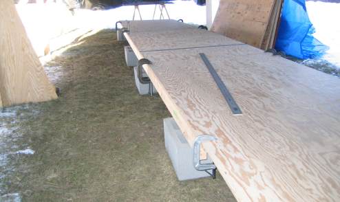
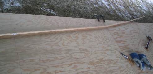
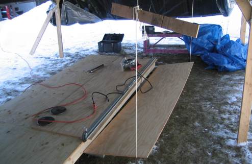
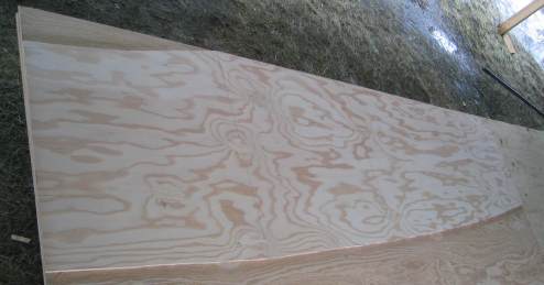
I placed three 3/8th's inch sheets of plywood end to end on the building table and clamped them down. I have to transfer the measurements from the plans of the sides and the bilge panels to the plywood. In this instance, I will draw all three port side sections on the left half of the plywood and the starboard bilge sections on the right half. Two-feet of plywood are to be cut off each end of the assembled line of plywood to be used for seats in the cockpit. I plan to omit these seats from Intrepid to gain more cockpit space. Mr. Michalak says these seats do not add much to the boat structurally. The smooth side of the plywood, what I will face to the interior of the boat, is positioned upwards.
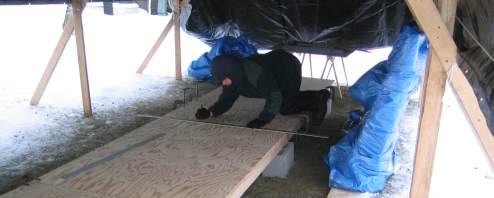
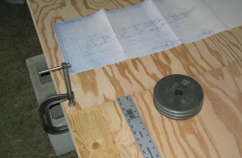
There I am, hard at work plotting all the key points. I will later connect all of the points into the actual lines of the panels that I will cut out. You can tell it is warming up a bit, I don't even have my winter coat on.
Mistake 1 -- no foul.
Corrected.
Mistake 2 -- foul.
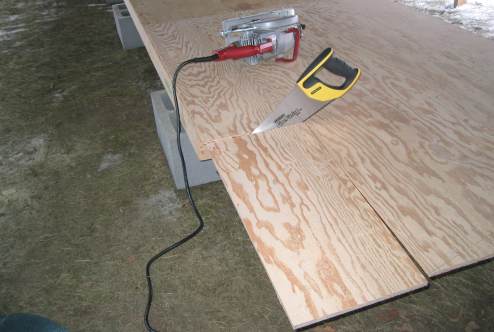
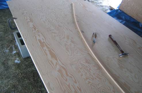
I used the circular saw to begin the cut for stern side, and finished the cut with a hand saw. I will use the circular saw to cut the top of the side next.
Oops.
Now, I could easily fix the error by redrawing and re cutting a different plywood panel, except I only purchased exactly enough wood for the boat
and the lumberyard did not have any more in stock. But with thoughtful rearranging of the plywood layout patterns, I find that I should be able to
use the mis cut front panel for another section of the boat. I may not have to buy another sheet of plywood after all.
I am re drawing the port stern side, but instead of aligning the edge of the plywood with the building table as before, I've aligned it with the side coaming line from the mid panel. I need to conserve every inch of plywood for these next few cuts to make sure I have enough wood for the boat. Looks like I will be happy again.
Here is one method of getting some help holding up the piece being cut off so the saw does not bind. I simply looped a line around the plywood and attached each end to the building shelter's support structure.
Mistake 3 -- This one's Mr. Michalak's -- no foul, but definitely a lot of head scratching. I wrote to Mr. Michalak with my concerns. I asked him to check his lines as I could not get a fair line. His response came quick, but left me holding the bag, as they say. Paraphrasing, he said, "I don't recall exactly how I did this one eight years ago, but when I lay the Mylar tracings [Dorado and Dorado B] of the two sides atop each other the chine lines match fairly well. Besides the customer I designed the plans for got a very nice boat out of it." That was it. I'm thinking, OK, son-of-a-gun, what the heck am I supposed to do with these plans now? They don't work.
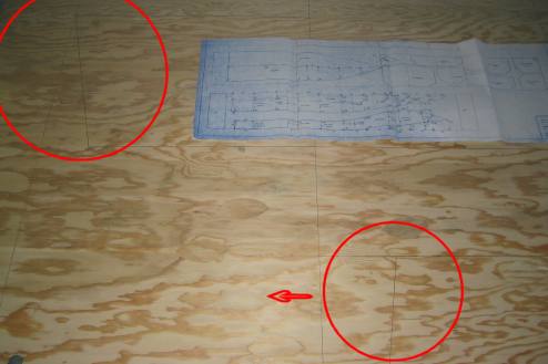
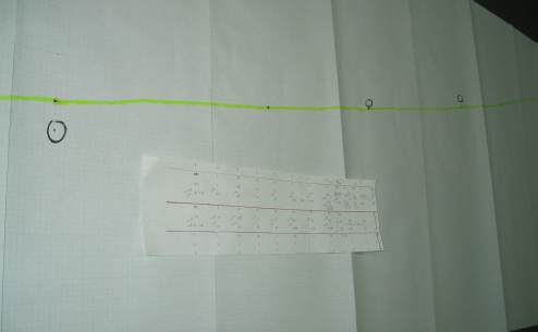
I decided to re plot the lines for both the Dorado and the Dorado B (I am building the Dorado B.) The green line in this photo shows the Dorado's
plot, adjusted for the increase in cabin size of the Dorado B. The circled dots represent where the plans of Dorado B deviate from the Dorado.
Clearly, I obtained a fair line from Dorado's plots. It would appear that three of the plots for Dorado B were incorrectly scaled from the original
Dorado for the Dorado B's plans.
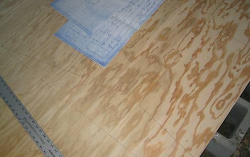
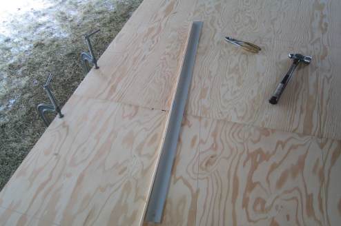
Drawing the lines to the corrected plots for the bottom side section.
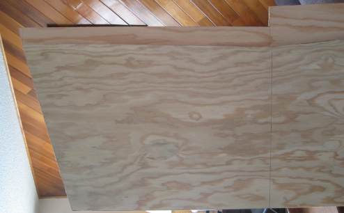
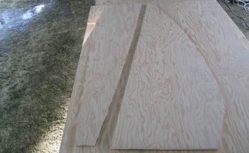
Now that I have the three port side sections cut out, as well as the three starboard bilge sections, it was a simple matter to trace their outlines to plywood panels for the opposite sides. This is a picture of the port mid side panel being used as a template for the starboard side.
Tracing the port bow side and the starboard bow bilge panel. Note that the bilge panel, in fact all of the bilge panels, are cut about two inches
oversize width-wise. Mr. Michalak recommends precisely cutting out the side panels and attaching them to the bulkheads. Then trial fit the oversized
bilge panels, and cut them to size.
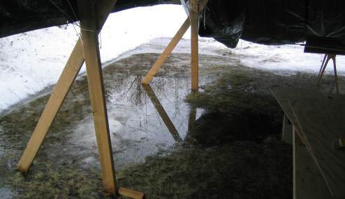
The warming trend continued. This was the beginning of the flood, and the Ark was not yet ready. Two and a half sides of my building table quickly became flooded. I could not have designed a better moat.... Half a week later, the temperatures went below freezing and my moat became an ice skating rink. At least I could walk around my building table again.
|