| The Voyage of INTREPID | |
| "Bow Plate" | |||
|
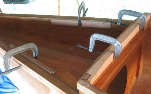
I would conservatively estimate that Intrepid is a little over a hundred pounds heavier than the plan's design weight. There were design considerations where either adequate information in the plans is lacking (for my skill level), or I just needed something to be beefier than originally called for. How I could decide to take such liberties in changing parts of the plans without having boatbuilding or design experience, is beyond me. I kept saying to myself, "Well, it seems to me that if it were this way, I would get this result." The bow plate is a good example here. I wanted something that I could stand on, with an anchor cleat that would hold in both high winds as well as when the boat was towed. I wanted a bow roller as well. I rationalized that real boats had bow rollers. I had thought of making a "pocket" in the bow plate just ahead of the cabin to hold my anchor rode, but experience now shows that that would have been a dumb idea for a single hander. Plus, that would have put a lot of weight up in the bow, with the 525-feet of rode that I carry. Although I can anchor in 75-feet of water, experience now shows that I don't really want to anchor in depths greater than 25-feet, for hauling up a lot of line is a lot of work. The first thing I did was to add the two pieces of wood inside the hull sides. Not only does this increase the "landing" area for the plate, but I wanted something other than the rub rail to mount to. The other piece clamped to bulkhead 4 is to support the forward end of the cabin panel assembly. I find myself often working on several phases of the project at the same time. No reason not to have mixed groups of components epoxied at the same time.
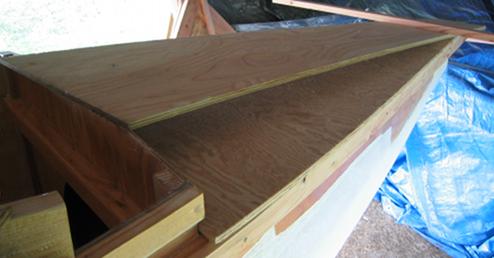
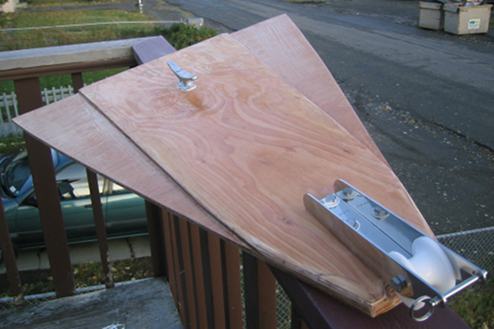
Test fitting the bow pieces. Just like the cabin panel, the rough bow plate panel was sized from the underside using the rub rail as a guide, then cut out using a circular saw. The length of the top plate is also being determined.
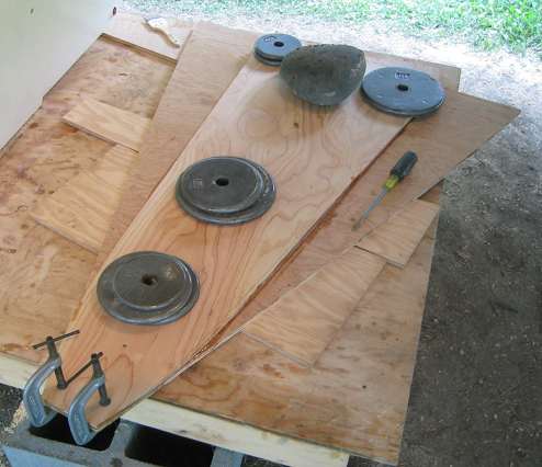
The top and bottom plates are being glued together. Yes, I am now adept at making: epoxy mix, epoxy glue, and epoxy paste, the latter two are determined by the amount of wood flour you add to the mixture.
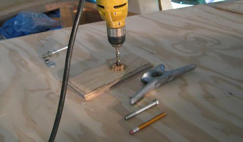
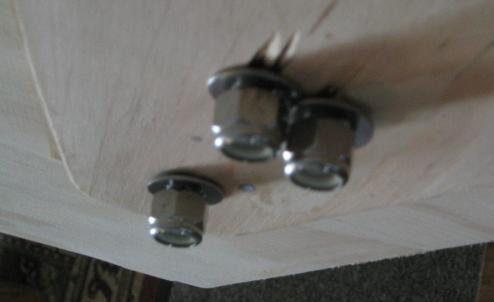
A backing block is being added to the bow plate for the 8-inch galvanized anchoring cleat. The cleat is through-bolted with galvanized bolts and will be bedded in a flexible sealing compound.
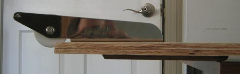
My new bow roller! Spendy stainless piece from West Marine. Notice how it is slightly set back.
For line clearance, I hollowed out a portion of the bow plate.
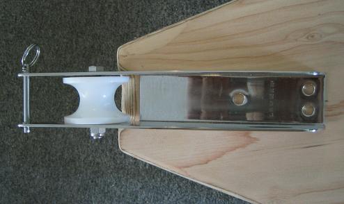
A second backing plate is used behind the bow roller. This plate also fits against the inside hull sides, adding support. Here I am using stainless bolts to hold the bow roller in place. When ever possible, you want to use the same types of metal together. The roller is bedded in the sealing compound.
The completed bow plate, coated in epoxy. When I am ready to install it, I will set the plate in the flexible sealing compound as well. This is to prevent leaks inside the cabin. I did not want to go with a permanent adhesive because I may want to remove the bow plate for some reason in the future. I also used 4 through-bolts and a number of stainless screws to attach the assembly.
|